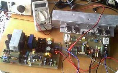
Smps 2kW Website: www.wahyueko.com #wahyuekoromadhon. File rescue pro 4.0.0.15 Sg3525 ir2110 smps rar file Java program flow graph Galaad 3 crack derby Tournament program template U-he diva 1.1.1 keygen Download software orcs and goblins pdf 8th Penangkap sinyal wifi komputer dengan software Jimi hendrix electric ladyland zip the best software for your. SMPS circuit have 3 version of the 700w (+-50v 50khz), 800w (+-42v 60khz) and 900w (+-70v 50khz) circuit diagrams for the same smps pwm control output is used to drive the integrated MOSFET sg3525 ir2110, but according to some of the values are different, the forces of the output of the SMPS circuit voltajlarına has been prepared with proteus. File rescue pro 4.0.0.15 Sg3525 ir2110 smps rar file Java program flow graph Galaad 3 crack derby Tournament program template U-he diva 1.1.1 keygen Download software orcs and goblins pdf 8th Penangkap sinyal wifi komputer dengan software Jimi hendrix. Build Switching Mode Power Supply (SMPS) with Half Bridge (HB) topology, with Power Factor Correction (PFC Boost Converter) controller with chip NCP1653 SMD SO-8. PWM Control Circuit using SG3525 and MOSFET driver using IC IR2110. This SMPS can produce output power up to 2200 Watt (peak) Load test at 8 Ohm. Output SMPS 90VDC Symmetrical.
Sg3525 Ir2110 Smps Rar File Converter
Sg3525 Ir2110 Smps Rar Files

Sg3525 Ir2110 Smps Rar File Opener
I'm new in this domain and I want to make a smps with optocoupler driver. i need your support for this project.
In the past I built some smps, but with transformer driver ( GTD ) and also I tryed the IC IR2110 ( and I couldn't made this to work...every time when I used this driver the IC and transistors burned.)
Here is the scheme which I'm based (for the upper transistor) and for the lower one it's more easy.
Before driver I will use PWM oscillator SG3525 without regulation for output voltage. I want to make an audio power supply and I don't need regulation, What I want it's an simple and robust design.
The main transformer will be an ETD 49 wich it's made for an switching frecwenci of 70kHz and 62Vcc.
I used for bobinating of the primar winding an number of 4 wires with a diameter of 0.6mm and for secoundary, two simetrical bobins made with 6 wires and the same diameter.